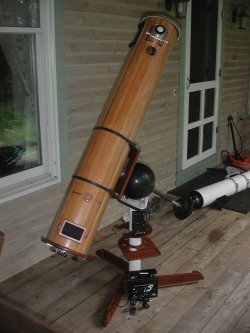
8" f/7 Flex Mirror Newtonian on a Driven Bowling Ball Mount
Bowling Ball Scope
A Winner!
Bowling Ball Scope
I set out to win an award at Stellafane 2006 with this scope, but as soon as I saw my competitors by the Pink Clubhouse, I knew my chances were slim. I figured that we might still have a chance in the optical judging category because of Colin's fine optical work. Turns out we had some trouble with the cell and had some astigmatism right at the time of judging, but we did win first prize in the special category!
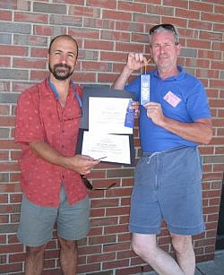
First Prize-Special Category
Let me start out by reiterating the age-old addage about "standing on the shoulders of giants". Much of what I've done in designing and constructing this telescope I got from pouring over the web pages of countless other ATM'ers, and I've tried to list all the pages of those people who's ideas I copied or used as a springboard for my ideas.
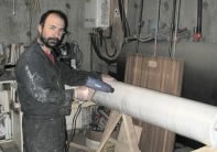
The Tube
The tube is built of coopered strips. I got the idea from Chuck Fellow's excellent website. I made a few changes, and have some ideas for improving on his process. First of all, because the tube is so long, it's a good idea to leave two strips on either side unglued at first, so that you can separate the two halves and scrape out the glue overruns on the inside of the tube before you glue the two halves together. Secondly, I'd use a few forms if I did it again. Chuck's method dispenses with any forms, and assumes that the bevel angle and hose clamps will make a nice round tube. . While the tube is round enough for the telescope application, it would have been more aesthetically pleasing to the touch to have it come out dead perfect round.
Take some time to tune up your tablesaw and do some research on cutting thin strips. Use a really sharp saw, and make sure that your fence is true. I ended up making a great jig to cut the strips without resetting the fence between cuts, that involved making a very thin pusher block. I used douglas fir and birch strips for my tube, and in order to get quarter sawn fir, I cut 3/4" boards out of a 4x4 so that when I cut the strips, they would be edge sawn.
Heat Shrunk Tube
I decided to add a layer of 3.6 oz. fiberglass cloth, and used a novel process involving heatshrink tape instead of vacuum bagging to get a good wetout. I ended up starving some of the cloth, so there are a few places that you can still see the weave. Don't skimp on the epoxy!
I made the endcaps out of 3/4" marine plywood that were cut out using router with a straight bit and a radius cutting jig. They have a rabbet on the inside lip that just fits the tube OD, and that really strengthens up the whole assembly.
The Focuser
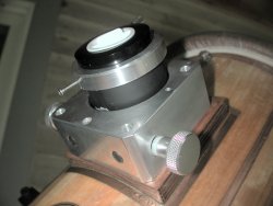
Enclosed Crayford Focuser
I really wanted to make an enclosed crayford-type focuser, and since I had access to a milling machine, I pretty much copied Jim Sapp's design. Here is his website. I did make my own CAD drawings, which was a great help in construction. Almost everything but the boring of the diagonal holes for the bearings was done on a drill press or a lathe, but Jim's page has a great workaround if you don't have a milling machine.
The Spider
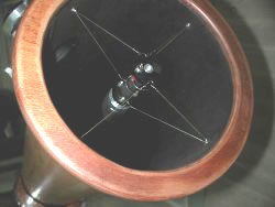
Wire Spider full size
I wanted a wire spider, but was put off by all those guitar peg designs, primarily because of the cost. I ended up using a pretty simple design that seems to work well. You can tunk on the diagonal holder and there's virtually no vibration. It's made out of the high E string guitar wire. The stuff is pretty strong. I also used pvc endplates on the diagonal holder spool so that I could insulate each wire from each other. I use the wires to run the secondary dew heater (just a resistor behind the secondary mirror in a little cavity in the aluminum). I made a plywood disk with a hole in its center to temporarily locate the spider spoolpiece while I was tensioning the wire. I cut out most of the circumference of the disk on two sides so that I could get my hands in to work the wire. Each wire is fastened to a hole in the spoolpiece end, then goes through a hole drilled in the tension bolt, and back to another hole in the other spoolpiece end, 90 degrees from the first end. I had to solder the twisted wire ends to keep them from slipping. I also had to solder a smal piece of wire across the vertex of the wire where it went through the tensioner bolt so that the whole thing couldn't slip from side to side through the tensioner bolt hole.
The diagonal holder is a virtual copy of Jack Schmidling's nice one, with a modification to allow for rotation of the secondary mirror since I don't have a center bolt and a traditional spider. I just cut the holder off about a 1/2" above the top of the diagonal face and tapped a 1/4-20 hole in the holder. I then drilled a countersunk hole in the other piece ( the one with the diagonal face) and put a belleville washer (sort of a spring washer) in between the two parts and tightened down on the flathead machine screw until there was enough tension to just be able to rotate the diagonal faced piece by hand.
The Mirror and Cell
I wanted to use my friend and fellow Central Maine Astronomical Society member, Colin Caissie's, flexed mirror cell design for this scope. I'd been impressed by his pioneering ideas on his 8" f/7 truss scope. He agreed to be the principle opician for my mirror, and did most of the grinding without me on the club's grinding machine. I was fortunate enough to help with the figuring.
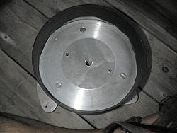
Mirror Cell
Figuring is all about getting the perfect spheroid. As those of you know who've tried to make traditional figured paraboloids, the final testing and figuring to deepen the center of a mirror is more a black art than a science. With flex mirrors, you figure that perfect spheroid, and then pull it into the perfect paraboloid.
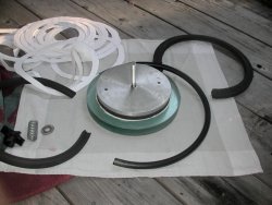
Puller Plate and Edge Gaskets
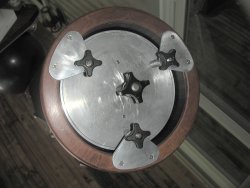
Collimation and Flex Knobs
Alan Alder has developed some software to design the puller plate and Colin has simplified the cell design. Essentially what we've done is to glue a piece of foam to the back of the mirror, andthen glue an aluminum puller plate with a captive bolt through a hole in its middle to that foam. Then we drop the mirror into a cell with alternating layers of foam rings and 1/2 O ring material to support the edge of the mirror. Finally we tension up the puller bolt against the back of the cell while star testing. When we get equal diffraction rings on either side of focus, we're done. Colin reports adjusting the puller tension a couple of times a year once the foam rings have settled in.
The Mount
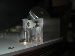
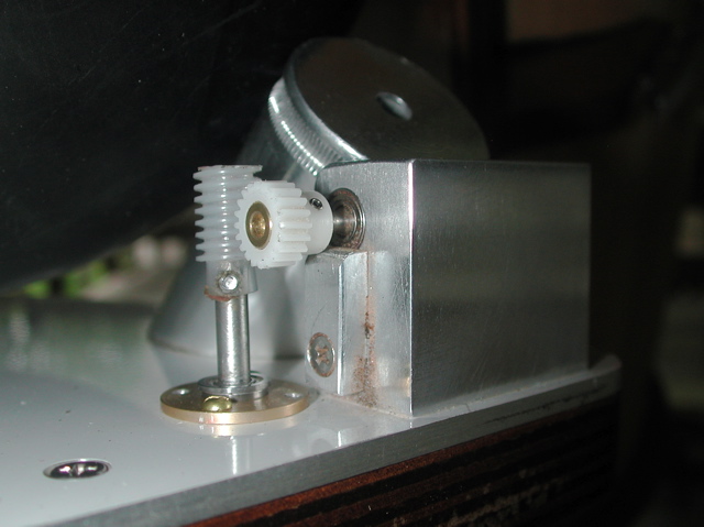
RA drive mechanism full size
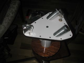
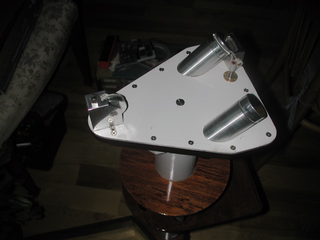
Drive Baseplate with Old Dec Wheel full size
I set out to be able to drive the mount in two axes, but after many prototypes, was forced to abandon the dec drive. I just couldn't get the right combination of stiction on the dec wheel with slip across the RA wheels. Again, my design is an adaptation of Johnson's design. The clever part is that the worm is cut right into the drive wheel. I cut the worm by running the drive wheel into a tap chucked up in my lathe. Very slick. This technique has also been written up extensively on the web.
The motor is a stepper from an old inkjet printer with some plastic gears to get the drive rate down to the right speed to drive the wormscrew. I still haven't solved all the vibration issues, so there is a very small periodic shake visible at high magnifications.
Overall Observations
This is a nice scope. It always draws folks to it because of the bowling ball. Really excellent optics contribute to the nice views. I've got to fix that drive vibration issue. I'm pretty happy with it, and it really is pretty transportable. The base weighs less than ten pounds, and the scope uncouples from the saddle with two quick disconnect latches, so everything ends up being easily carried. It's possible to carry the scope and ball combo for short distances, so that's what I do when I want to set it up in the yard. I enjoyed the project mostly because I built everything on the scope from scratch including the electronics.